
This post has been “upgraded” to a page where updates will take place – Ethernet Transmission Delay.
The “Ethernet Transmission Delay” of a packet is the time it takes to “clock out” an Ethernet packet (aka “Frame”) on a wire. On short wires and LANs this is by far the largest delay related to the actual wire-transmission. The clock-in at the receiver happens at the same time as the clock-out at the transmitter – so don’t double the value calculated. On longer wires, you also need to take the “Propagation Delay” into the equation. This is the delay of the actual wave-form as it moves with approximately 2/3 of light-speed.
Recently I needed to weigh pros and cons of the transmission delay against the payload. As often, I ended up in Excel.
Here’s the result:
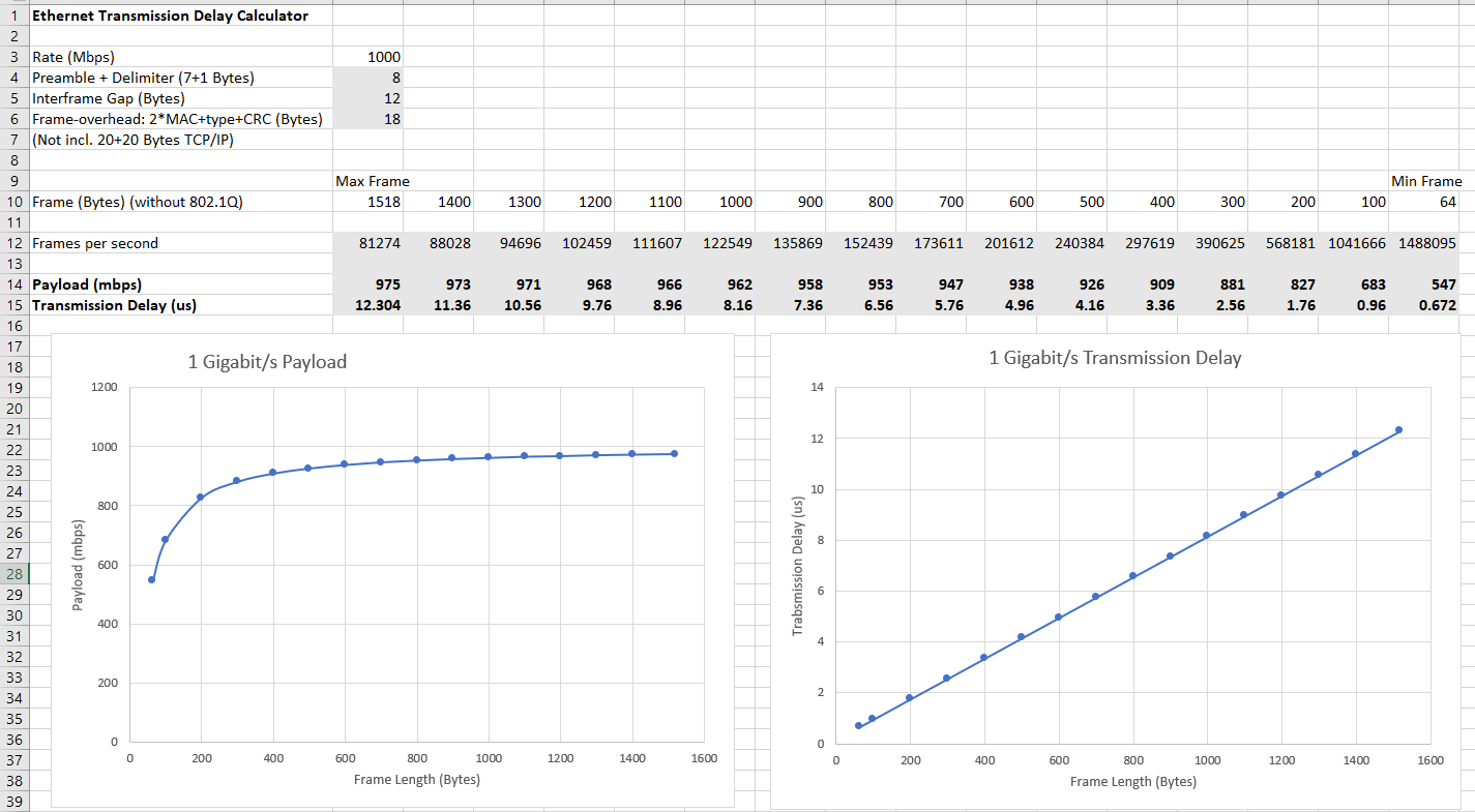
The Excel-sheet can be found at the Downloads page. I have not included TCP/IP headers in the overhead. As this adds 40 bytes, it significantly impacts the payload when using the shorter frames. If you want, you can easily change the Excel to include this by changing the overhead from 18 to 58 bytes.
Please note that there are also delays in routers & switches as well as in the software stacks. A typical switch is of the “store-and-forward” type. This means that the input side (aka “ingress”) will take the frame in and store it in a buffer, before the output side (“egress”) starts to transmit . This will add a similar transmission delay for every switch – but need not affect the payload. Also note that switches may have different transmission speeds on the various ports, and remember to use the right speed in the calculation.
There are also “cut-through” switches that starts the output as soon as the type field (and possible VLAN and QoS) is inspected. This saves most of the repeated transmission time.