
Introduction
Until recently, my professional interest in electric motors was mainly how to measure their noise. Now I am digging a little deeper. Not only the controls, but also the actual motors have developed much since I was in university. On this page I will look at the overall functionalities of the main variants.
Classic DC Motor with Brushes
As a kid I inherited my fathers Meccano toys. These included some better looking versions of the worn one in the picture below.
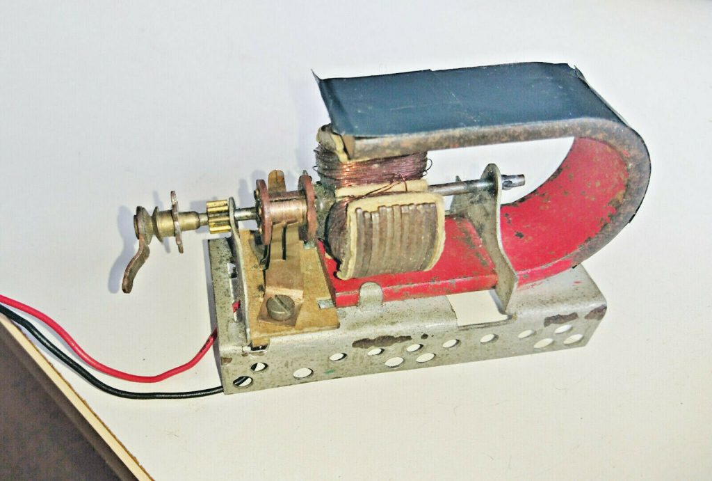
Even for a kid it was relatively easy to see how it worked – at least to a degree:
The two wires (from a small battery) are connected to two metal flanges. These connect to a kind of “drum” – fixed to the rotating axis. Gaps in the drum splits it in three. The three rotating windings are connected at each end to a part of the drum.
The correct term for the drum is “commutator” and the flanges are normally known as “brushes” – even though they typically are realized by small pieces of graphite held in place by metal springs. The rotating part is fittingly called the “rotor” while the outer stationary part in similar manner is called the “stator”. In the Meccano motor the stator is a horseshoe magnet. Stators are typically a bit more complex, but the overall concept is perfectly illustrated here. While we are at the terminology; the motor on the picture is an “in-runner” because the rotor runs inside the stator. This is the most common variant, but there are also “out-runners” (fans on a PCB are often out-runners). Finally this motor is “single-excited” – meaning that it only requires power to the rotor. Larger motors would require DC power to the stator and would become “double-excited”.
Running the Brushed DC motor
The diagram above is just a diagram. In real life the commutator is on the axis of the rotor – but away from the magnetic field. Like on the Meccano motor.
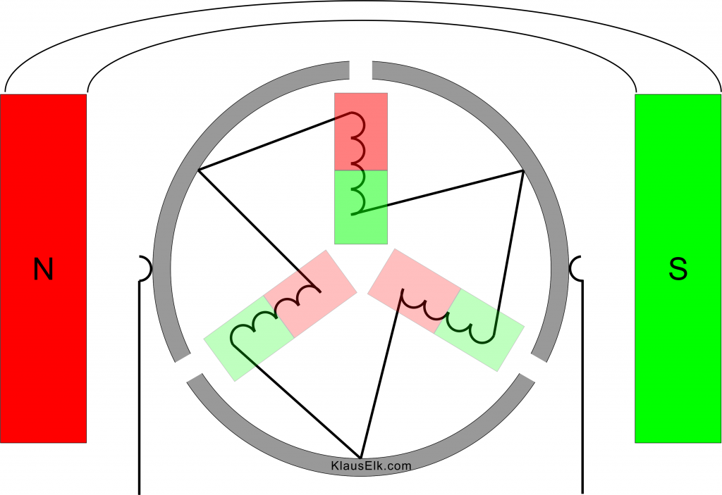
When power is applied, the magnetized part of the rotor will turn clockwise as it is attracted to/repelled from the stator poles.
Considering the wiring, it is clear that while one current runs through one winding in one direction at the top, another runs – serially, and therefore halved – through the two other windings in the opposite direction. If we e.g. have + on the left brush, the top winding will have current flowing towards the center, while the two others will have current from the center and outwards.
On the figure this results in one electromagnet at “12 o’clock” and two – more vague – magnets at 4 and 8 o’clock. For each winding this means that it receives a current I one third of the time and I/2 in the opposite direction two thirds of the time.
In the figure below the rotor has turned clockwise a bit and the commutator has changed the paths of the currents. Now the winding at app. 5 o’clock receives the full current, while the two others get half. Note that only the winding at app. 9:30 has changed polarity, because this is the only one that has changed the direction of the current. As can be seen, this fits exactly with what we need in order to keep the clockwise movement.
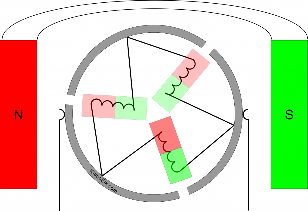
After 120 degrees of turning, the brushes will touch upon new parts of the commutator again and currents will find new paths, and the currents and magnetic fields will look as in the first figure again.
If you swap the wires to the battery, the motor runs the opposite way.
Note how the commutator acts as a built-in mechanical position sensor – and control!
There are rotors where the commutator is only split in two, and thus supports two windings. This creates two problems: 1) There is a risk of a deadlock at start if the rotor is in balance between stator poles. 2) The brushes may briefly short-circuit when alternating.
Thus my Meccano DC engine was actually less primitive than it could have been.
Using the Brushed DC Motor
Brushed DC motors will eventually wear down their brushes, but they are nevertheless remarkably robust. In some scenarios end-users can replace the brushes. If you turn a motor like this mechanically, it will produce a current. This is exactly the concept in the older car generators (ignoring the “dynamo” versus “generator” naming). I have replaced brushes in my older cars. I have also experienced that the generator stopped charging, and a few whacks with a big hammer loosened the jammed brushes. A fix done in a few minutes – including fetching the hammer.
In bigger motors the stator is typically not a permanent magnet, but also created as one or more electromagnets. The interesting thing is that if the same supply is used for both rotor and stator (serially, parallelly or in a combination) the motor works as good with AC as it does with DC! This is called a Universal Motor. Some of the early power tools, kitchen machines etc. where created this way.
The speed of a brushed DC motor is easily increased by turning up the voltage.
The 3-phase Stator
Before we look at asynchronous AC motors, synchronous AC motors and brushless DC motors, we will take a look at the 3-phase rotating field which can be found in the stator of all the afore mentioned motors. We also have 1- and 2-phase versions, but I focus on 3-phase variants here.
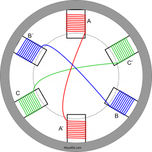
While the rotor typically only has two poles, the 3-phase stator often has many. A good and simple example is a 6-pole stator, which we can describe with help from an analog clock. If the three phases are called A, B and C, the poles are e.g., wound with wires as follows:
12 o’clock: A
2 o’clock: C’
4 o’clock: B
6 o’clock: A’
8 o’clock: C
10 o’clock: B’
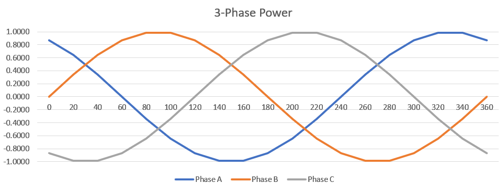
The three original phases are distributed 120° from each other. The wire from phase A starts at 12 o’clock and is wound around the pole there. Then it continues to the pole at 6 o’clock and is wound around it – in the same circular way. This creates two identical electromagnets with north and south in the same direction – seen from outside. However, when the magnet at 12 o’clock has north towards the center (and the rotor), the magnet at 6 o’clock will have south towards the center – and vice-versa. The same naturally goes for phase B and C and their opposing poles, B’ and C’. See figure below.
The Rotating Field
In the table below, the first column contains row-names of our stator-poles, relating to the 6 positions of our “clock” from before. The remaining columns represent a time axis, where the time is given as degrees of the frequency in the three phases. We end in 360° – the same as 0° where we started. I have “sampled” every 60° (more is found in the original Excel – see the downloads page) as this will give one phase with zero current – and thus no magnetism. This clarifies the picture, and prepares us for later. Whenever a pole is north, the opposite is south – and non-magnetic poles also oppose each other.
Looking at the diagonals in the table, it is clear that we have a rotating field. We start with north at the top of the “clock”. As time goes by, north moves clockwise round – and so does south. Between them we have a non-magnetic zone. If we swap any two phases, the field will instead turn counter-clockwise.
| Position | 0° | 60° | 120° | 180° | 240° | 300° | 360° |
| 12 | N | – | S | S | – | N | N |
| 2 | N | N | – | S | S | – | N |
| 4 | – | N | N | – | S | S | – |
| 6 | S | – | N | N | – | S | S |
| 8 | S | S | – | N | N | – | S |
| 10 | – | S | S | – | N | N | – |
It is probably no surprise that a wire has two ends. With three phases we have a total of six wire-ends. This gives us two alternatives:
- Connect one end of each of the three wires together inside the motor (e.g. A’, B’ and C’). This creates an internal virtual ground. The three remaining wires are led to the three external power-phases. This is a Y-coupling.
- Lead all six wire-ends to external screw terminals. An electrician can now chose between a connection as either a Y or a Delta.
Asynchronous AC Motor
One of history’s most popular electric motors is the Asynchronous AC Motor. These motors are used in factories and households all over the world. Some call them the “workhorse of the industrial revolution”. They are also called induction motors. This is because the problem of transferring electricity to the rotor part is solved by not doing it! Instead the rotor is created in such a way that the magnetic field from the stator generates currents in the rotor – which then again produces an electromagnetic force that interacts with the stator. The most common type of rotor is a “squirrel cage” – a construction, where the “wires” are thick aluminum or copper bars – short-circuited at the ends. This is shown below in a GIF from Wikimedia.
The GIF shown has three pole “pairs”, which actually are not pairs!
When the 3-phase power wires are connected to the motor, a rotating magnetic field is created as described earlier. The rotor turns almost as fast as this field. The percentage of the speed that it is behind is called the “slip”.
If you could give the rotor a push up to the same speed as the rotating field, there would be no induced currents and it would fall back – until the currents are strong enough to (almost) follow the field. Enforcing the load on the motor results in a growing slip- and with it an enforced torque. Thus we have a very stable and adaptive rotating machine. The speed is defined by the frequency of the connected power-grid – 50 Hz or 60 Hz – divided by the number of stator pole-pairs and reduced a few percent by the slip. Multiply by 60 for RPMs. In the US an asynchronous motor with three pole-pairs, will thus have a speed a few percent short of: 60 Hz * 60 seconds/minute / 3 pairs = 1200 RPM.
Using the Asynchronous Motor
The weakness of asynchronous motors is that the speed is not easily varied, and gears may be needed.
The upside of asynchronous motors is that they are very robust. Contrary to the classic DC motors, there are no brushes – the rotor is “self-excited”. Asynchronous motors handle varying loads very nicely and connect directly to mains.
Synchronous AC Motor
A synchronous AC motor has a stator that creates a rotating magnetic field in the same way as on an asynchronous/inductance AC motor. The difference lies in the rotor. The rotor in a synchronous motor does not rely on an induced field. Instead it has a permanent magnet, or an electromagnet with its own DC power-supply. In the latter case “slip-rings” are typically used to transfer the current to the rotor. These look much like the commutator on a brushed DC motor – but without the gaps, and the current does not alternate.
With a rotor based on a magnet, the rotor will normally follow the rotating field of the stator without any slip. Hence the name Synchronous Motor.
Using the Synchronous Motor
Clearly slip-rings is a robustness issue when comparing with the asynchronous motor. Thus permanent magnets is the preferred choice. The drawback here is that historically these have not been very powerful. This is changing now with modern materials.
When the asynchronous motor experiences a heavier load, the slip and the torque grows. Synchronous motors does not have the same nice feature. When experiencing a higher load the synchronism fails and the engine stalls.
This is probably one of the main reasons why synchronous motors have been preferred where the load was relatively small and stable, and where synchronism in itself was an important feature. A good example is older wall-clocks. Many factories, schools and other institutions had loads of wall-clocks with a 1-phase synchronous AC motor. During day-time many power-grids have problems with maintaining the specified frequency, and for years it has been normal praxis to regain the lost cycles at night. For the sake of the many synchronous AC motor driven clocks. I am not sure this is still something they do.
When a synchronous motor is run directly from mains you cannot vary its speed. The RPM follows the formula previously given.
With modern radio-controlled watches, lack of robustness and no real speed control, the classic synchronous motor – run from mains – does not have a bright future.
Brushless DC Motor
Until now we have mainly discussed classic electric motor designs. This changes with the Brushless DC Motor. As the name says, it has no brushes. It turns out that the term “DC” is somewhat misleading.
Not only are there no brushes. The motor has also been “turned inside-out” as the rotor is now typically a permanent magnet, while the stator is where we connect the wires from a commutator.
In reality the brushless DC motor has given new life to the synchronous AC motor. As stated earlier, modern technology gives us more powerful permanent magnets. Most brushless DC motors are therefore the same as PMDC motors – Permanent Magnet DC Motors.
Modern technology has also given us solid-state switches (e.g. FETs) and other electronics. This means that we can “chop up” a normal DC supply into three phases. These are supplied to the stator as shown earlier. When the chopping is very advanced, it creates sinusoidal waveforms, but more often the simpler trapezoidal waveform is used. Still the table for north, south and un/magnetized phases follow the table we saw under the “3-phase Stator” heading.
With these electronics we are suddenly able to control the speed of the synchronous AC motor – sorry – the brushless DC motor. Simply by switching faster or slower.
Implementation of the brushless DC Motor
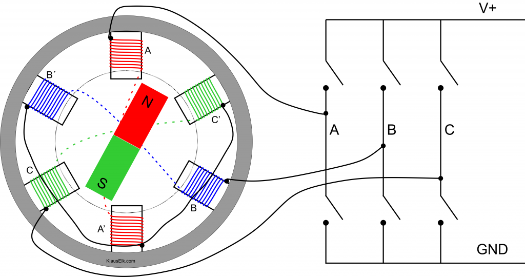
The figure above shows the 3-phase stator we saw earlier – now internally connected in a Y. We also have the permanent magnet rotor. To the right we see the external electronic commutator. When this commutator use the trapezoidal waveform it will change every 60° – as our “magnetism” table earlier on this page.
When we revisit the magnetism table we can see that there is always:
- One set of opposing poles without magnetism
- Two neighbor sets of same opposing poles. E.g. at positions 10 and 12 o’clock we have north, and thus at 4 and 6 o’clock we have south.
The way the poles are wired up, two neighbors always represent one phase and another inverted. As they have the same magnetic polarity, one phase must have a positive current, while the other has a negative similar current.
Walk-through of specific position
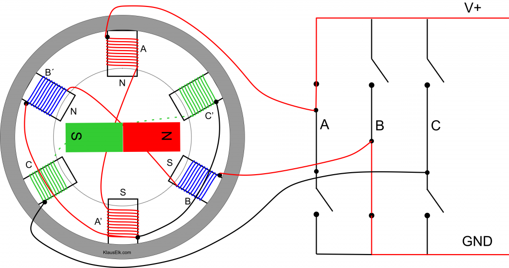
The figure above shows the rotor pointing it’s north towards 3 o’clock – having recently passed the pole at 2 o’clock (now neutral). To pull the rotor further clockwise, we need the stator to have south at 4 o’clock. Also having south at 6 o’clock stabilizes the torque produced and keeps noise down. In the “magnetism” table we can see that this corresponds to a stator field rotated 300°. Looking further back at the sines graph, we see that at 300°, phase A is positive, B is negative and C is zero.
Looking at the schematics we see that we will get this – in a digital form – when we close the top switch in the A leg and the bottom switch in the B leg, while the four remaining switches stay open. The motors internal Y-connection completes the circuit. The active current-path is colored red in the figure above.
We saw that we got the necessary currents by closing one switch in the top row and one switch in the bottom row – in another leg. The third leg is inactive. This gives us three choices in the upper row. For each of these we have two choices in the bottom row – giving us six legal combinations. This fits very nicely with our switching each 60° – remembering that a full circle is 360°.
The final drawback of the synchronous AC motor was it’s sensitivity to increased loads. When the rotor goes out of synch with the rotating stator field, the engine stalls. Again modern electronics comes to our aid. With the help of cheap Hall-sensors or similar, we can track the rotor position and regulate the rotating field of the stator – e.g. slow it down if the rotor cannot keep up. The position sensors also raises the efficiency of the BLDC motor. This is however at the cost of one more thing that can fail.
Instead of Hall-sensors, it is possible to utilize the “Back EMF (electro-motoric force)” in the passive phase – C in the drawing above. We can close this loop – not to the power-lines, but to a measuring circuit. At low speeds there is too much noise, but in that case we can often run open-loop – without feedback.
Using BLDC Motors
We can regulate the speed over a very large range. This is e.g. practical in fans. Running fans at the lowest sensible speed gives less noise and uses less power. Fans are often created as “out-runners”, where the stator is fixed on a PCB (smaller fans in electronics) with the control circuit, while the fan-blades has built-in permanent magnets and rotates around the stator.
Without the brushes there is no dust from the graphite. This is highly appreciated in disc-drives and other sealed systems.
Advanced Motors
Tesla and other car companies are competing in more and more advanced motors. Often they mix the traits from some of the classic engines above, to obtain hitherto unseen efficiency and performance. When I get wiser I might write more about these…
There are many nice videos on YouTube showing the above animated and colorized.
Some good links:
https://en.engineering-solutions.ru/motorcontrol/induction3ph/